Project title is “AUTOMATIC ROOM LIGHT CONTROLLER WITH BIDIRECTIONAL VISITOR COUNTER “.
The objective of this project is to make a controller based model to count number of persons visiting particular room and accordingly light up the room. Here we can use sensor and can know present number of persons.
In today’s world, there is a continuous need for automatic appliances with the increase in standard of living, there is a sense of urgency for developing circuits that would ease the complexity of life.
Also if at all one wants to know the number of people present in room so as not to have congestion. This circuit proves to be helpful.
CIRCUIT DIAGRAM
RECEIVER CIRCUIT

The IR transmitter will emit modulated 38 kHz IR signal and at the receiver we use TSOP1738 (Infrared Sensor). The output goes high when the there is an interruption and it return back to low after the time period determined by the capacitor and resistor in the circuit. I.e. around 1 second. CL100 is to trigger the IC555 which is configured as monostable multivibrator. Input is given to the Port 1 of the microcontroller. Port 0 is used for the 7-Segment display purpose. Port 2 is used for the Relay Turn On and Turn off Purpose.LTS 542 (Common Anode) is used for 7-Segment display. And that time Relay will get Voltage and triggered so light will get voltage and it will turn on. And when counter will be 00 that time Relay will be turned off. Reset button will reset the microcontroller.Microcontroller based Visitor Counter.
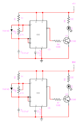
TRANSMISSION CIRCUIT
This circuit diagram shows how a 555 timer IC is configured to function as a basic monostable multivibrator. A monostable multivibrator is a timing circuit that changes state once triggered, but returns to its original state after a certain time delay. It got its name from the fact that only one of its output states is stable. It is also known as a 'one-shot'.
In this circuit, a negative pulse applied at pin 2 triggers an internal flip-flop that turns off pin 7's discharge transistor, allowing C1 to charge up through
R1. At the same time, the flip-flop brings the output (pin 3) level to 'high'. When capacitor C1 as charged up to about 2/3 Vcc, the flip-flop is triggered once again, this time making the pin 3 output 'low' and turning on pin 7's discharge transistor, which discharges C1 to ground. This circuit, in effect, produces a pulse at pin 3 whose width t is just the product of R1 and C1, i.e., t=R1C1.
IR Transmission circuit is used to generate the modulated 36 kHz IR signal. The IC555 in the transmitter side is to generate 36 kHz square wave. Adjust the preset in the transmitter to get a 38 kHz signal at the o/p. around 1.4K we get a 38 kHz signal. Then you point it over the sensor and its o/p will go low when it senses the IR signal of 38 kHz.
PCB LAYOUT


DOWNLOAD
CIRCUIT DIAGRAMS-DOWNLOAD
PCB LAYOUT-DOWNLOAD
PROGRAM-DOWNLOAD
REPORT-DOWNLOAD
For Upload Your Project Here Send Me On My Email Id:
parthdave34@yahoo.com

did u have softcopy for pcb layout?
ReplyDeletenice dude..........
ReplyDeleteplease told me how to burn the source code to the microcontroller at89s52
my email id is - gorutiwari@gmail.com